Eecs:1100 Digital Logic Design Final Examination Eith Answers - Dr. Anthony D. Johnson, The University Of Toledo Page 4
ADVERTISEMENT
 1
1 2
2 3
3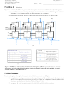 4
4 5
5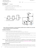 6
6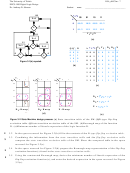 7
7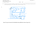 8
8The University of Toledo
f15fs_dild7.fm - 4
EECS:1100 Digital Logic Design
Dr. Anthony D. Johnson
Student
name
______________________________________
Problem 2
10 points
Figure 2.1 contains the following parts of the description of a universal (bidirectional) shift-register:
(a) a partial (incomplete) drawing of a logic circuit model of a universal shift-register is shown
in Figure 2.1(a), where positions of input terminals are not shown;
(b) one specific Function Table of a universal shift-register is shown in Figure 2.1(b).
O
O
O
O
3
2
1
0
Q
Q
Q
Q
RES
RES
RES
RES
D
D
D
D
CLK
CLR
MUX
MUX
MUX
MUX
S
s
s
s
s
1
1
1
1
1
4:1
4:1
4:1
4:1
s
s
s
s
S
0
0
0
0
0
3
2
1
0
3
2
1
0
3
2
1
0
3
2
1
0
I
SR
I
SL
I
I
I
I
3
2
1
0
(a)
Signal
Operation code
Signal description
Register operation
designation
S
S
1
0
Serial output for
0
0
no change
O
shift left operation
3
0
1
parallel load
Serial output for
1
0
shift left
O
shift right operation
0
1
1
shift right
(b)
(c)
Figure 2.1 MUX-based implementation of a Universal shift register. (a)Partial logic circuit model of a universal
shift register. (b)Function table of the shift register, showing the operation codes to be implemented by the design.
(c)Space for writing in the answer to part 3.2.
Problem Statement
Based on the given description from parts (a) and (b) demonstrate an ability to:
1. complete the missing connections to the signal inputs of the multiplexers in the logic circuit
model of the universal shift-register in such a way that the completed circuit implements the
functions specified in the Function Table of Figure 2.1(b);
2. recognize the serial output terminals for shift-left and shift-right operations.
ADVERTISEMENT
0 votes
Related Articles
Related forms

 - The University Of Arizona")


Related Categories
Parent category: Education